From the HOQS community. This write-up first appeared in Guide 6 (Operation & Gear) of the HOQS Facebook group and is republished here with permission. Read the original post.
Quick checklist before the gig
- Sub count sized for +10 dB real-world low-frequency headroom
- Box tuning below the long-duration bass fundamentals in your set
- HPF/LPF set, polarity and timing aligned
- Peak limiter at or just below amp clip or the driver’s program rating
- RMS limiter validated at AES/4, then tested up to AES/2 if temperatures allow
- Chain gain staged, with no red lights anywhere
- IR thermometer packed; log motor temps every 15 to 30 minutes in rehearsal
- DJ briefed on meter discipline and headroom
The full write-up
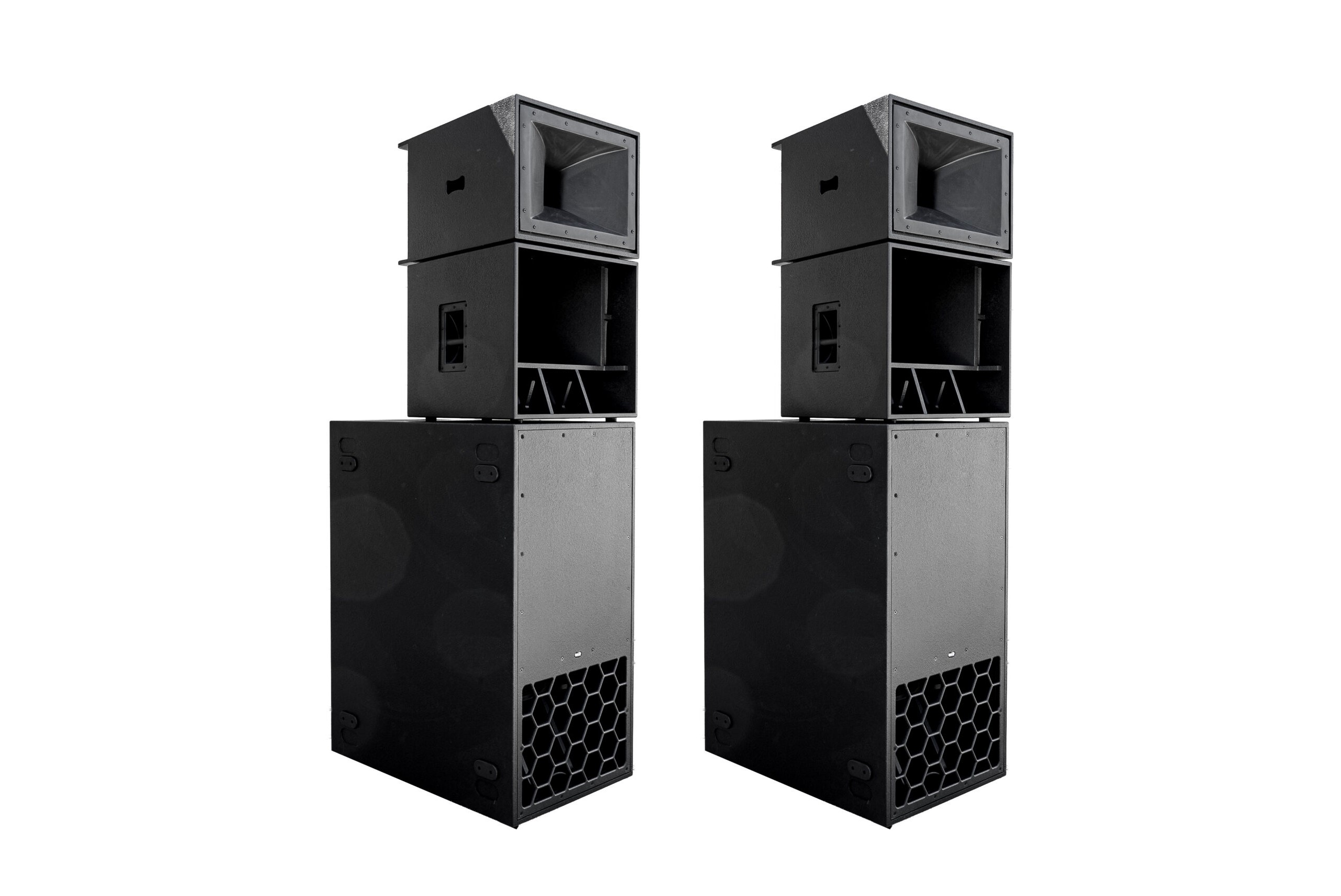
Let’s talk about strategies to manage thermal buildup (heat) on the motors of your subwoofers in a PA rig being played at party levels and beyond for the entire duration of long gigs. It is primarily (and most importantly) a matter of having enough subwoofers to keep up with your tops, but there are some related details which are also worth mentioning.
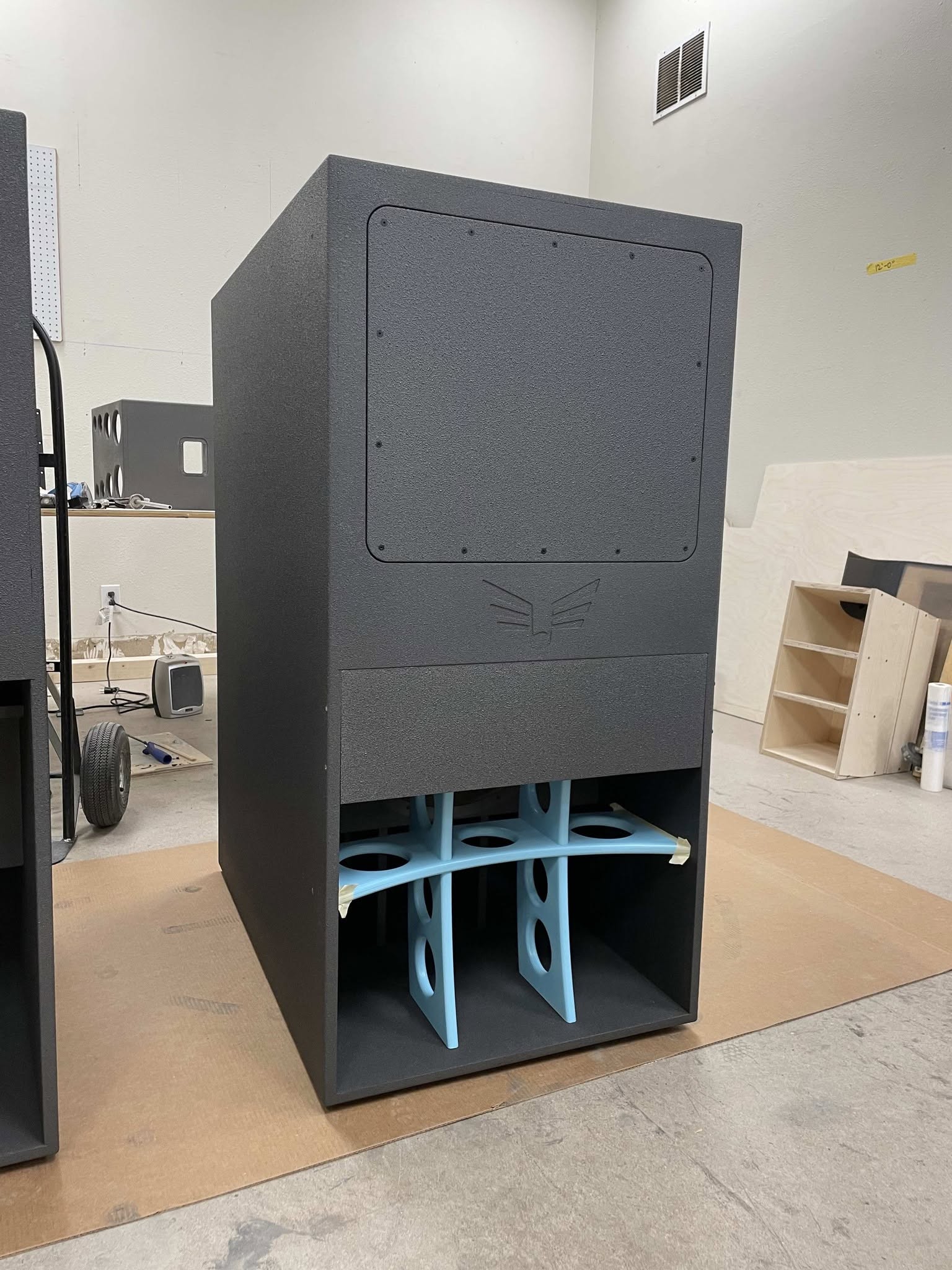
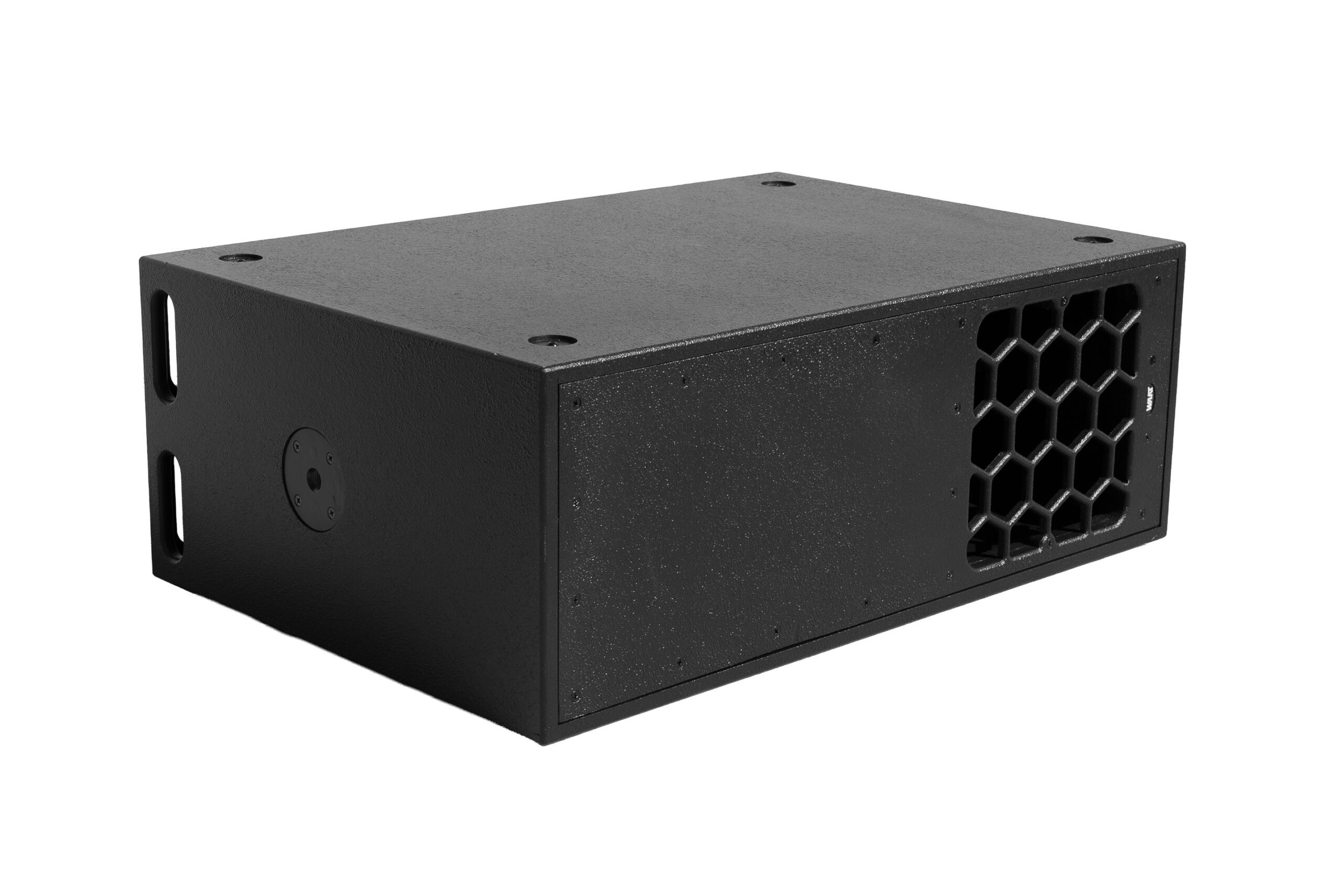
I will start off by saying that since Paraflex cabinet designs often make the driver’s motor easily accessible for touching, this feature allows us to be more aware of the magnet structure’s heat status (which is also the case with many tapped horn cabinet designs). This is very different from FLH folded horn subwoofers or scoops (or many other common cabinet types for that matter), so most users of traditional folded horns or scoops are largely oblivious to just how scorching hot their driver’s motor may become when subjected to sustained high average power levels. “Out of sight, out of mind,” right? Ignorance is bliss, right? Well no, we are better than that. Let’s live with a high level of awareness so we can resolve our issues. Face our demons! Let’s grab the bull by the horns! Sound transformatively good to you? Ready to grow and evolve?
Alright, here we go.
In the following text we will establish some rough guidelines for creating a PA speaker system which can reliably withstand and perform in a highly taxing and challenging (yet not uncommon) scenario without suffering from excessive thermal compression losses and without burning up or damaging drivers. This worst-case scenario is described below, and we will delve into how voice coil size and quantity are important, as well as the number of cabinets, their type, size, and ratio. There is something to be said about excursion minimums with associated electrical impedance features, and how a correlation of these contributes to current draw and heat generation. We will also touch upon limiter settings.
Many who have built or own the Paraflex 1×12 or 2×12 tops can tell you that they are very capable PA mid-tops which can keep up with multiple subwoofer cabinets. In fact, if you take a single Paraflex 2×12 top and use it with a single Paraflex 1×18 subwoofer, you will find that it is fine at low to moderate levels, but when you push this little system to raucous party volume, the subwoofer will at some point begin to show signs of heat buildup on the motor (or some other form of strain) before the 2×12 top even begins to approach its limits. This simply means we have an imbalance of available headroom.
This imbalance is exacerbated when the music being played is a very bass-heavy style with a low crest factor (meaning a high average level, dynamically compressed) and sustained basslines with fundamentals (sines) located on and around the frequencies where the subwoofer’s electrical impedance minimums and excursion minimums coincide. This is the “worst-case scenario” promised above (the graphic below explains the issue visually).
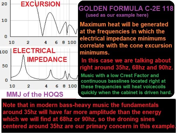
If the music you play happens to have droning basslines focused heavily at 35 Hz, then selecting a subwoofer cabinet with its fundamental tuned to 35 Hz is a recipe for thermal problems. We can avoid this for the most part by having the cabinet tuned a bit lower. Our Paraflex Silver Formula C-2E, the C-2E.3 (which can easily be adapted for a 21″), and the original C-2E 1×21 are all tuned fairly low, and the angle-brace update can be implemented with them. The Paraflex C-2E 2×15 also has a lower tuning option in the plans, and the Paraflex CRAM! 2×15 (such as the one Bradley Steven Katz built) is tuned low as well.
The peak-hold spectral analysis charts below show the distribution of energy in some very bass-heavy tracks. Note where the bassline’s energy is centered, and the difference in amplitude referenced to the level at 90 Hz: 20 dB, 19 dB, and 17 dB are all massive discrepancies. Even a more conservative 15 dB suggests a power multiplication factor of 32, which in theory means that if we cross over from our subwoofers to our tops around 80–90 Hz, our subwoofer system would need to handle 32 times more power than our tops (to make up for the 15 dB difference) to play this sort of music at very high levels without the subs running out of headroom before the tops reach their maximum output.
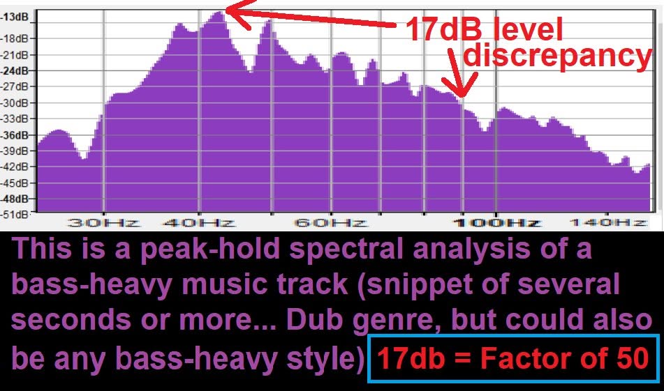
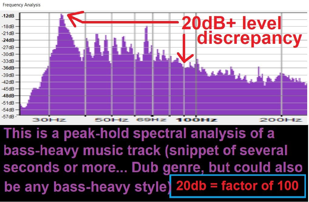
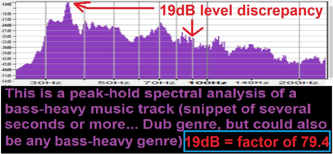
That suggests we’d need a heck of a lot of subwoofers to keep up with only one or two tops. It is true that we need a lot of subwoofers for extreme SPL, but the real world is more forgiving than this line of reasoning suggests. About 10 dB is much closer to what we really need to make up for in a critical high-SPL application (10 dB is a power multiplication factor of 10, easy to remember).
The type of music you play, at what level, and for how long, are all determining factors. The ratio recommendations below are based on the “worst case” heavy-bass, low-crest-factor, high-SPL scenario described above.
Recommended cabinet ratio guide
One way to figure out what you need is to follow some rough top-to-subwoofer ratio guidelines:
- Paraflex 1×12 top (G#1 style): a 1:3 ratio with Paraflex 1×18 subwoofers, or 1:2 with our Paraflex 1×21 or 2×15 subwoofers using recommended drivers. In other words, a pair of these 1×12 tops can run with six Paraflex 1×18 subs or four 1×21 (or 2×15) subs to come close to matching available headroom.
- Paraflex 2×12 top: double the subwoofer counts given above for the 1×12.
- Paraflex Type “A” 1×12 subwoofer: two of these, loaded with recommended robust drivers, are nearly equivalent to one Paraflex 1×18 sub; three are nearly equivalent to one Paraflex 1×21 or 2×15 sub.
- Paraflex 1×15 subwoofer: two are roughly equivalent to one Paraflex 1×21 sub.
- Paraflex 2×8 top: loaded with capable 8″ drivers, nearly equivalent to the Paraflex 1×12 (G#1 style) top. High-passed a bit higher (or used with kick bins) it gains headroom.
The drivers used will always shift these numbers, so treat them as approximations, not rules set in stone. They’re useful for guidance and perspective, and they help you invest wisely: matching headroom means your money is spent more effectively, highly important when resources are limited.
Bending the cabinet ratios
If you’d like to skew the ratios toward fewer subwoofers, choose drivers with higher power handling for your subwoofer cabinets, or choose a Paraflex subwoofer design that uses multiple drivers. Generally speaking, that means larger-diameter voice coils or more voice coils per cabinet (or 18Sound’s Tetracoil). A superb, practical example that has been built in multiples is the Paraflex C-2E 2×15 loaded with dual 15DS115 drivers (there’s an adaptation that shifts the driver baffles over slightly to give the 15DS115 pole vents more breathing room), a marvelous combination with tremendous power density for a Paraflex. Less radical, less costly examples: an NTL5000 in the Silver Formula C-2E, or one of the 6″-coil 21″ drivers such as the NSW6021-6 or 21SW152 in the Silver Formula C-2E or Golden Formula C-2A 1×21.
Less can be more when it comes to processing
Paraflex subwoofer systems tend to sound best and perform optimally with very little processing on the subwoofer channel, or none at all, other than the recommended high-pass and low-pass filters. Classic hardware like the BBE Sonic Maximizer or Aphex Aural Exciter isn’t needed, which is a great opportunity to simplify your amp rack (perhaps freeing room for another amplifier). This isn’t only about sound quality: anything that takes away from the dynamics of your low-frequency content while boosting the average level of low-frequency energy near your cabinet’s fundamental tuning increases the potential for thermal buildup. This doesn’t apply to what a DJ does on their side when an occasional anemic track needs its bottom end fattened up, that’s fine, since it’s applied selectively and only when called for.
Be diligent about preventing clipping
Make sure none of the stages in your signal chain are being overloaded. Any component pushed much too hard becomes a source of clipped (flat-topped) waveforms, which are notorious for overheating voice coils. If your DJ is driving the mixer’s output meters into the red, take action to prevent it, and make up for it with additional gain in the system’s later stages if necessary. Keep a spray bottle or squirt gun handy and squirt the DJ every time they hit the reds, as if you’re training an unruly kitten. Be consistent; show no mercy.
Limiters, and how to set them to protect a subwoofer system
Last but not least, limiters are an essential feature if you want to do everything you can to protect your subwoofer system. Trusted manufacturers such as Danley and Powersoft offer a lot of guidance here, so their tutorials, explanations, and formulas are well worth checking out. We’ll cover the most basic of basics with a common two-part limiter system: a peak stop limiter and an RMS limiter, each with a very specific function. The goal is to control average power levels while fully preserving the music’s crest factor (its dynamic nature), and the key to success is in the settings.
If your DSP limiter system is separate from your amplifier (not integrated), this procedure can either be calculated or, if you prefer the manual approach, done with a trusty AC voltmeter and a tone generator set to 50 or 60 Hz. Disconnect your speakers from the amplifier and connect the AC voltmeter to the output of the channel you’re setting the limiter for, with the amp’s gain controls fully clockwise.
The peak stop limiter is much like the clip limiter built into many amplifiers. Its purpose is simply to keep your amplifier from clipping on peaks, or, if your amplifier is massively overpowered for your driver, to protect the driver from mechanical damage. Modern heavy-duty, high-excursion subwoofer drivers can withstand some absurdly high peaks, so setting the threshold to limit peak output to the driver’s “Program” or “Music Program” rating is reasonable. If your amplifier doesn’t have that much voltage available, set the threshold closer to the driver’s AES rating (some brands say “RMS” or “Nominal,” which are close enough to AES for our purposes, more on that below). The peak stop limiter’s time constants should both be extremely short, practically instantaneous, and the ratio should be very high (infinity, or “brick wall”).
A word on power ratings. Driver manufacturers don’t all use the same standards or terminology for power handling, which can cause confusion. Comparing ratings across brands is apples to oranges. We can gain a foothold by understanding the AES 1984 power handling standard and using it as a reference. The AES rating is determined by the driver surviving a two-hour trial in free air fed pink noise filtered to cover a decade of spectrum (20–200 Hz, for example). Pink noise is dynamic, with a crest factor of 6 dB, a vitally important detail (6 dB is a power multiplication factor of 4). That means the conservative average component of this power handling is more like AES divided by 4. Remember this; we’ll put it to work later.
Not all brands use AES, but reputable ones have their own alternative that comes close (said to be off by no more than 30%, usually less), and we don’t need absolute precision for this job. Respected names like Eminence and B&C also use filtered pink noise over a few hours, which is why ratings aren’t far removed from one another. Some brands call their standard “RMS,” others “Nominal” or “Continuous,” but all are roughly equivalent to AES. “Program” or “Music Program” ratings are basically AES + 3 dB, i.e. double the AES rating (3 dB is a power multiplication factor of 2). We don’t need to concern ourselves with “Peak” ratings, which add yet another 3 dB. There are other standards out there, but these are the ones you’ll meet most often with modern PA drivers.
The RMS limiter is set up to behave like an intentionally slow leveler (AGC). Its very long time constants are what let it retain the music’s vital crest factor. Find your RMS limiter’s attack, release, and ratio settings (they’re sometimes labeled differently):
- Attack: very long, 2,000–3,000 ms (2 to 3 seconds).
- Release (sometimes called “decay”): at least 2× the attack time; some prefer 4× to 6×.
- Ratio (if available): high, at least 6:1, up to 10:1 or more.
We’re creating a very slow limiter that intentionally does not respond to peaks. Since the AES rating is determined with pink noise that has a 6 dB (factor of 4) crest factor, imagine what’s left if you removed the dynamics from that pink noise: a level of about 1/4 (25%) of the AES (or equivalent) rating. That’s our safest, most bulletproof starting target for the RMS limiter.
For the last step, drive the system with the full-strength test signal and adjust the RMS limiter’s threshold while watching the voltmeter until the output hits the voltage that corresponds to 25% of the driver’s AES (or equivalent) rating. Then stop the signal, disconnect the meter, reconnect the speakers, and play music at party volume for a few hours (or play a gig). If the driver motors aren’t getting hot to the touch, great: repeat the procedure with the threshold set for 1/3 (33%) of the rating, and test again at war volume for a few hours. Still running acceptably cool? Fantastic, try 1/2 (50%) next, and so on.
If a driver’s motor ever feels uncomfortably hot to the touch, you’re surely experiencing thermal power compression losses, which is a sign to back off the average power level. If the outside of the motor is hot, the inside is even hotter. If you’d rather be extra nerdy about it, ask the driver manufacturer for the maximum recommended operating temperature (measured at the magnet structure or wherever they recommend) and check it with an infrared thermometer.
The safe average power (as a percentage of AES) differs from system to system and situation to situation because of many variables, some covered above, like the character of the music and how it interacts with the cabinet design, the length of the show, and differences between rating systems (some drivers are rated more optimistically than others). Even ambient temperature and humidity have some influence.
Calculating target voltage: multiply the desired long-term power limit (watts) by the nominal impedance (ohms), then take the square root. For example, 117 V is 1,700 W into 8 Ω; 82 V is about 850 W; and half of 117 V, 58.5 V, is 425 W. Notice that half the voltage works out to one quarter (25%) of the power. Prefer a calculator? Use an Ohm’s law calculator.
Mark Tomlin of Linea Research (also the HOQS Regional Support Director for the UK) suggests the Linea Research method for determining RMS limiter attack time: “100/HPF frequency. So if you have a high pass at 45 Hz it would be 100/45 = 2.22. Then set the release at 2 or 3 times the attack depending how much protection you want.”
Limiter time in dB/s instead of ms? Don’t panic, divide 3,250 by the time in milliseconds. A 10 ms attack ≈ 325 dB/s; a 4 ms attack ≈ 800 dB/s.
Tried RMS limiter settings on your own drivers? Tell us what percentage of AES (or equivalent) has worked well for you in the HOQS group.
Further reading
- Original post with full image set (HOQS group)
- Limiter guidance from Powersoft (HOQS group)
- Limiter guidance from Linea Research (HOQS group)
- Bennett Prescott (B&C): AES 2018 presentation (PDF)
- More loudspeaker fundamentals from Bennett Prescott
Building or running PARAFLEX subs? See every published cabinet and HOQS driver in the HOQS Knowledge Base, or ask a WAAT builder.